S2 Network Node Wiring Diagram
Wiring diagram in the front casing, there is an on/off button with led indicator which is used to toggle switch on and off or carry out inclusion, exclusion, reset or association. Replace the plastic cover on the junction box to ensure that no hot leads are exposed.

diagram of wireless mesh network IOT Wiring Diagram
S2 netbox application modules, or blades, connect to the i2c bus of an s2 network node.

S2 network node wiring diagram. To set up an output: Setting up outputs set up an output for each portal's lock. In the diagram above it may be possible to install one s2 netbox and wire all the system resources to it, but that may require running numerous wire lengths over considerable distances.
Xbee s2c rf module features. S2 netbox user guide created from s2 netbox help version 4.8.01 february 2016 s2 security corporation one speen street suite 300 framingham ma 01701 www.s2sys.com s2 support: S2 network nodes (s2nn) are the connection points for card readers, monitoring points, relay outputs, and temperature points.
S2 security netbox acp solution. Site layout or distances may make a node installation desirable. It hosts the web server database server data storage and application logic.
Genetic interaction networks highlight mechanistic connections between. S2 access blade wiring diagram written by susie friday, june 18, 2021 add comment edit. Another illustration how to wire the esp8266 as server and client mode, therefore there is no need to use a router or smart phones to interact/communicate to the esp8266, this is direct communication between 2 esp module as server and client mode, ones the code is loaded the esp8266 coded as server the client esp8266 will automatically connect to the esp8266.
W2, aux and or e (emergency) wiring connections will normally connect to the ecobee3 w1 terminal. It may be faster, easier, and less expensive to place an s2 network node at one S2 security netbox acp solution.
The module act as a mesh network with each other. Gene pairs whose profile similarity exceeded a pcc > 0.2 were connected and graphed. The global network illustrates how coherent sets of genetic interactions connect protein complex and pathway modules to map a functional wiring diagram of the cell.
Single phase 3 wire submersible pump control box wiring diagram submersible pump electrical circuit diagram submersible well pump. S2 security corporation netbox installation guideversion 2.0s2 security corporation6 abbott roadwellesley, ma 02481www.s2sys.com ul listingul 294 listing for the s2 netbox is pending.note to installersinstall according to national and local codes and use only ul listed equipment.fcc noticethe s2 netbox complies with the limits for a class a digital device,. The nodes address is set either using dial or dip switches on the device, or can be configured using the bus on the basis of software.
The maximum length of the devicenet cable depends on the selected cable type and baud rate, although it cannot exceed 500 m. A global network of genetic interaction profile similarities (a) the essential similarity network was constructed by computing pearson correlation coefficients (pccs) for genetic interaction profiles (edges) of all pairs of genes (nodes) in the essential genetic interaction matrix (exe). The neutral wire must be connected to the same side of the junction block.
On the blade diagram, click the 3. See the download cut sheet at: S2 netbox ® checklist packing.
Electric hoist wiring diagram harbor freight electric hoists electrical circuit diagram attic lift. A maximum of 64 network nodes can be used per fieldbus segment. Blades are automatically rcognized by the node,
It implies that it has not been assigned a node id and can not O ethernet connection linking two pieces of electrical equipment. It can communicate up to 400ft in the closed area but in line to line sight, it can communicate up to 4000ft without any interference.
S2 bt1 3v br/cr2330 j1 5v 3.3v 2 3 4 1 s1 vbat in1 k 1 k 2 k 3 k 4 k2 k1 k4 k3 in2 in3 in4 in5 in6 in7 in8 8v j6 j2 j5 j7 pass 12v gnd dat d0 tb8 1 bzr vo d flt gnd tmp gnd vin tb1 led d1 clk 2 d1 led vo bzr gnd clk d0 dat tb9 no out 1 c nc no out 2 c nc nc out 4 c nc no no. Lenels2 24 july 2019 s2 netbox initial software setup guide setting up portal access control for more specific information on these wiring configurations and resistance values, see the section on connecting inputs in the installation guide for your s2 node.

In Silico Fragmentation of the LN Networks (A and
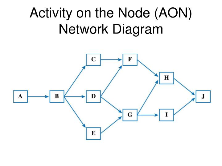
30 Activity On Node Network Diagram Wiring Diagram List

Node identities across datadriven modules and their

S2 System Wiring Diagram schematic and wiring diagram

New Options for High Availability using HyperV with
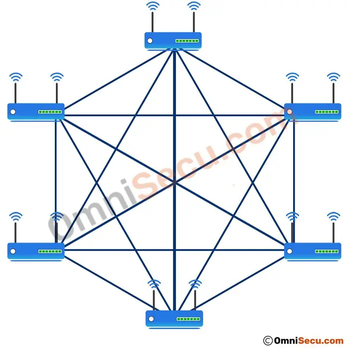
diagram of wireless mesh network IOT Wiring Diagram
30 Activity On Node Network Diagram Wiring Diagram List
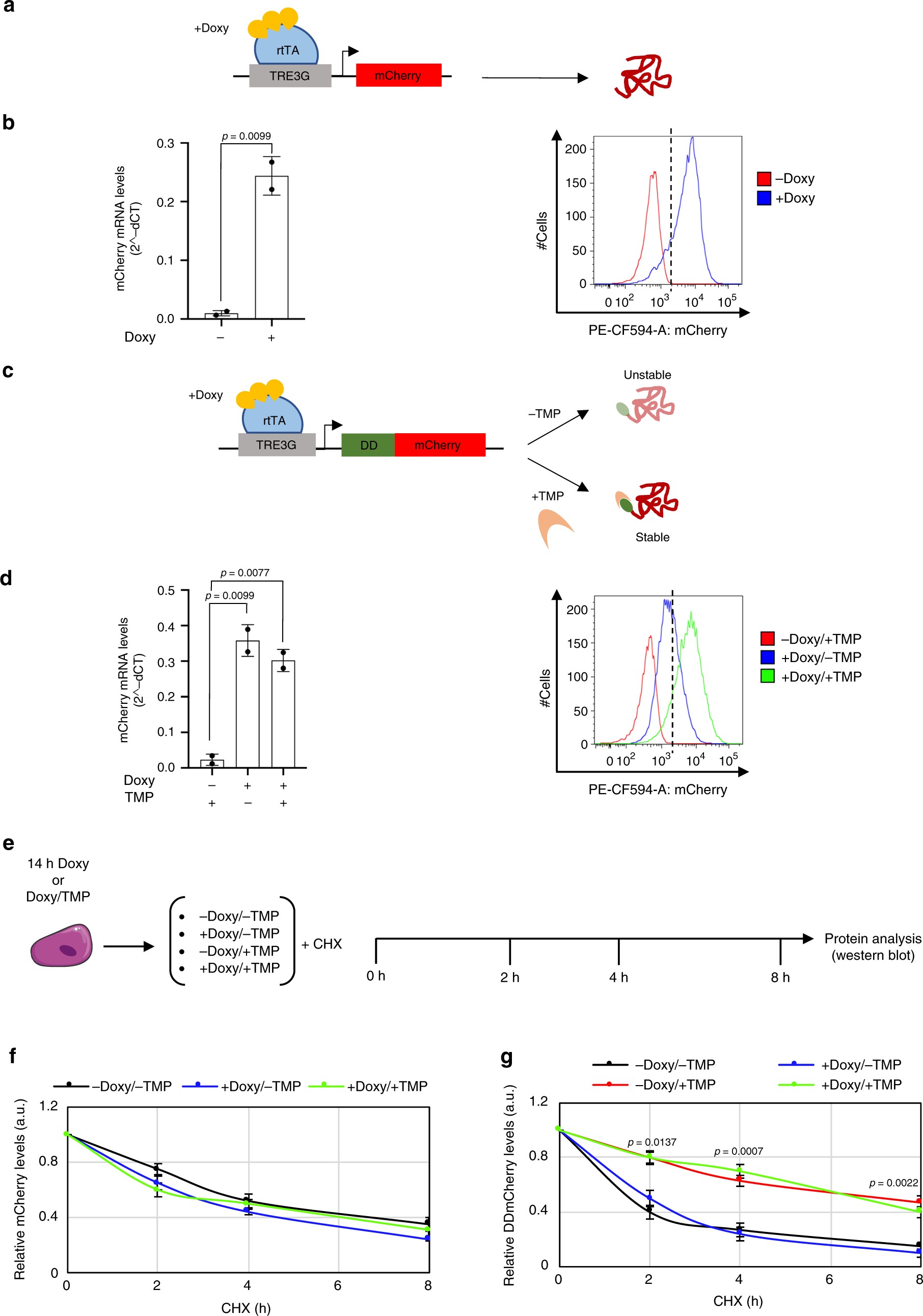
Dish Network Dual Node Diagrams My Wiring DIagram

New Options for High Availability using HyperV with
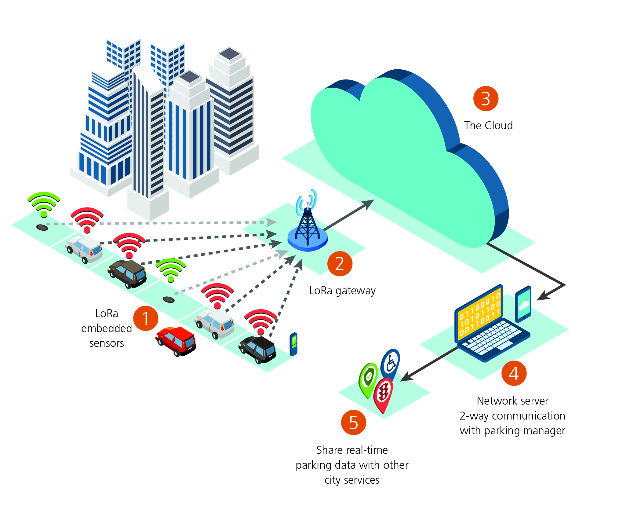
Long Range Wireless Network Diagram Wiring Library

(a) Bayesian phylogram (95 majority rule consensus tree
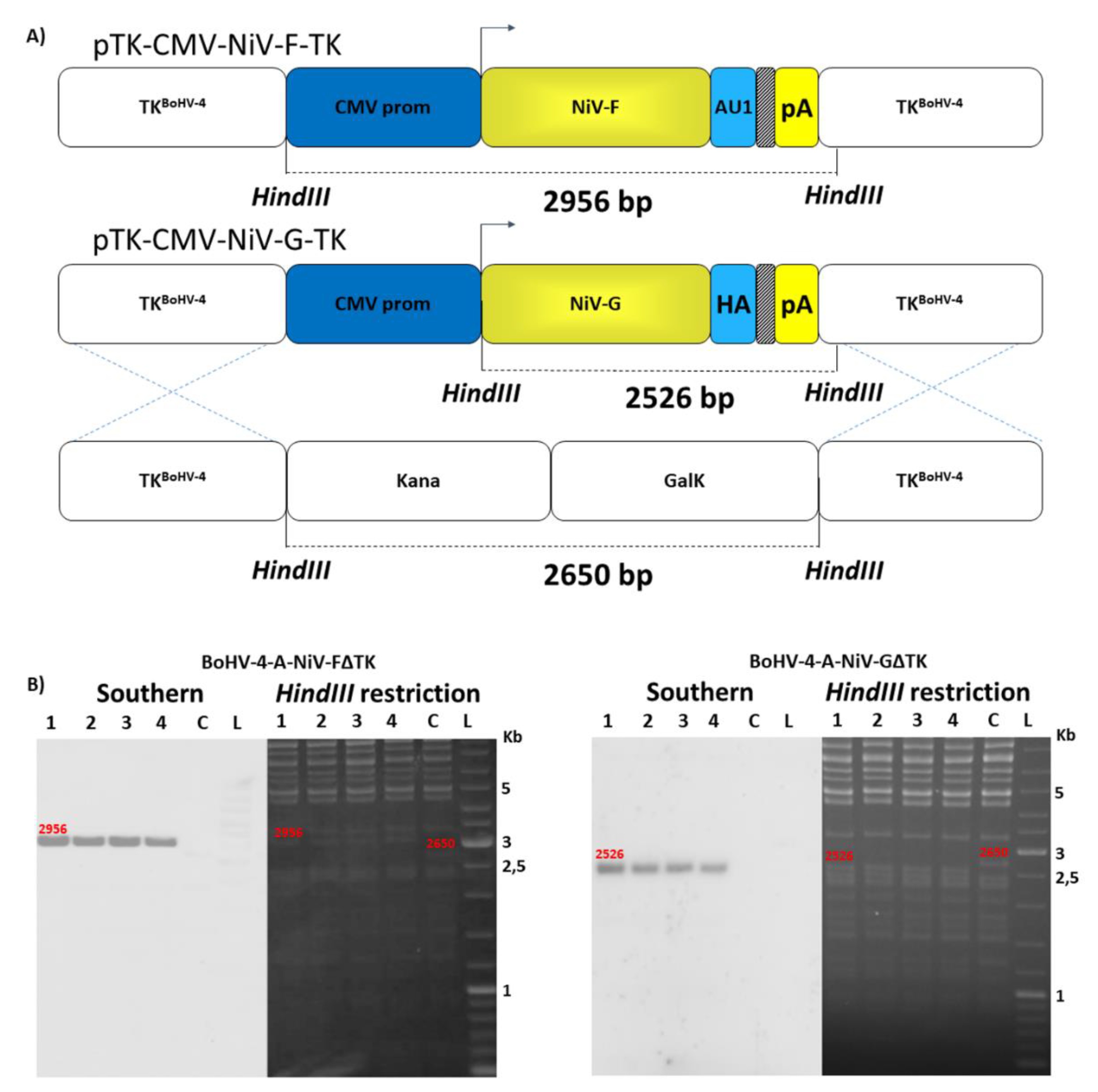
Dish Network Dual Node Diagrams Wiring Diagram Image
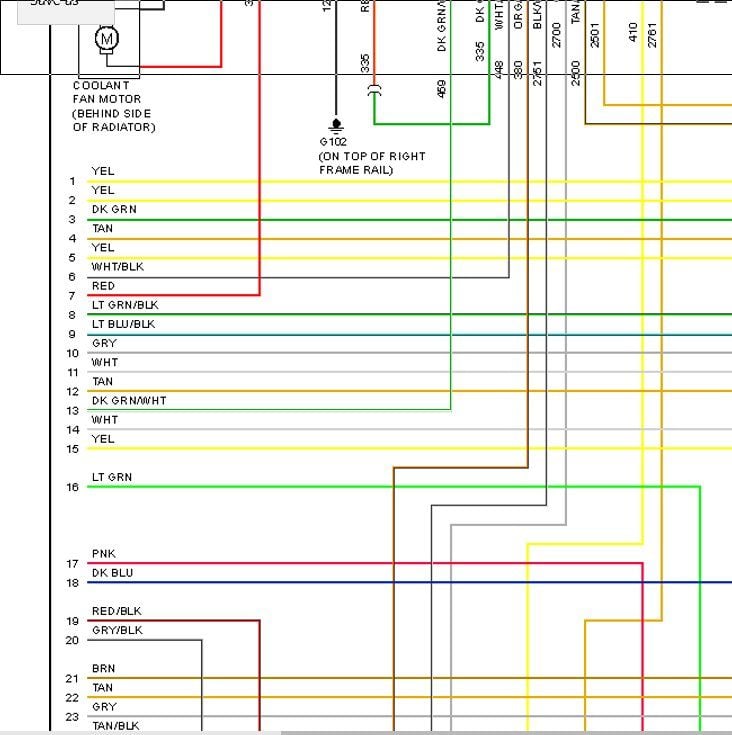
Gm Wiring Diagram Color Abbreviations Irish Connections
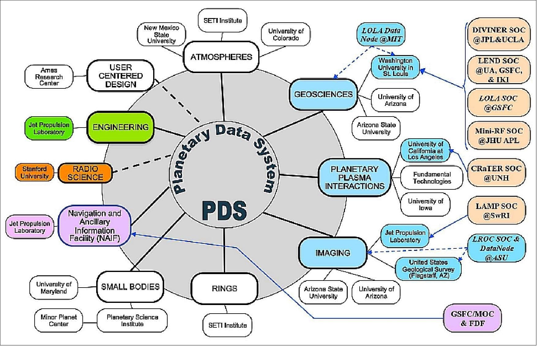
Dish Network Dual Node Diagrams My Wiring DIagram


